
Pixel Peeping
Introduction
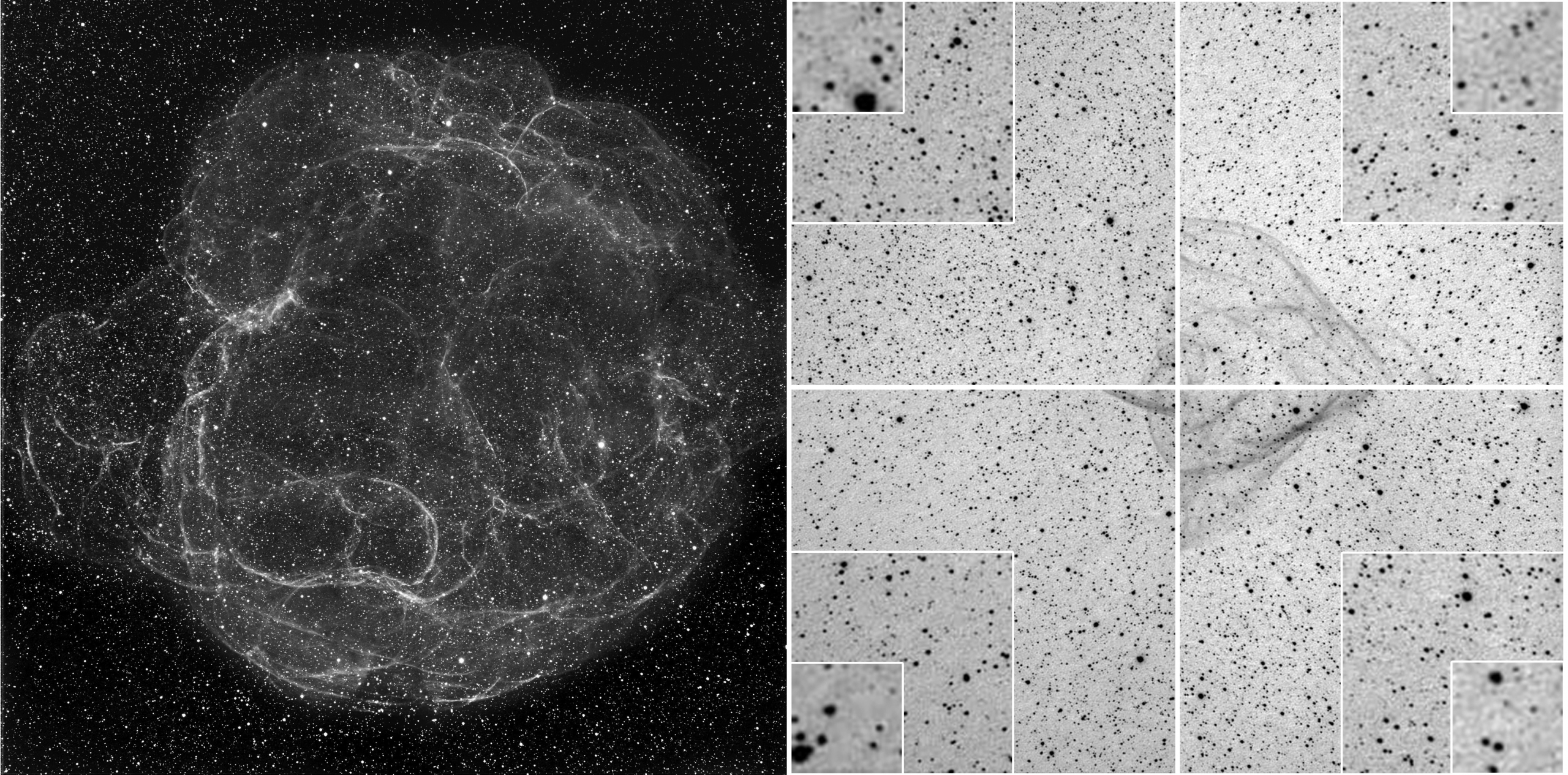
To the uninitiated, the habits of wide-field astrophotographers must seem peculiar: they spend hours imaging an object through their scope, then take more images with the scope cover on, then again with a white t-shirt over the lens, after which they disappear for hours in front of their computer to combine and finesse all those images using software wizardry. When done, they seemingly ignore the grand, wispy object taking up the frame and proceed to judge the quality of the whole image by zooming way in to the corners to look at the shape of the stars. Sometimes the stars at the extreme edges aren’t too good which causes the astrophotographer to spend hours going over the hardware and trying to square their results with Nyquist sampling theorem predictions.
Based on our experience viewing countless image corners, this blog contains some concrete advice on achieving the best images with your gear.
First, we need to learn what a stellar point sources is and how to calculate how many pixels your camera uses to image one. This leads into a discussion of the Airy Disc and FWHM.
Airy Disc and FWHM
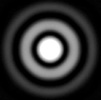
The Airy disc is the size of the smallest pin-point of light that your telescope can produce. Its diameter varies by the wavelength of light and the focal ratio of the telescope. For instance, a faster focal ratio scope will produce a smaller Airy disc than slower scope (the lower the f/# the “faster” the scope), and, blue light will produce a smaller Airy disc diameter than longer wavelength red light in the same instrument. The theoretical appearance of the Airy disc, through a circular aperture at high magnification, is a compact central dot with alternating rings of dark and light emanating from the dot. This is known as the Airy pattern. Outside of the theoretical world, telescope quality, appropriate magnification, atmospheric turbulence and dispersion, and sky glow will affect the visibility of the stellar Airy pattern to just the first, and maybe the second diffraction ring at focus.

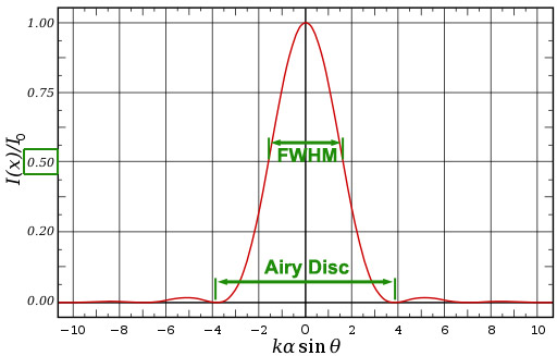
The red curve below is the graph of the of the percentage of light contained within the Airy disc and successive rings. According to the Handbook of Astronomical Image Processing, 2nd ed. (by R. Berry & J. Burnell, p. 8): “nearly half of the image-forming light is concentrated in the small, bright central core of the diffraction disk, a much smaller region defined by the diameter at which the light has fallen to half its central intensity. This region is the Full-Width at Half Maximum (FWHM) of the diffraction disk”. The FWHM and Airy disc widths are indicated in the graph. In the computer-generated image of the Airy disc and Airy pattern above, the FWHM would be just the central part of the Airy disc.
Size of Stellar Point Source
The Handbook (p. 29) suggests using the FWHM, the bright central diameter of the Airy Disk, as representing the size of stellar point sources.
Image Sampling
The concept of “sampling” describes how many pixels it takes to reveal the smallest detail in an image. For night-sky imaging, the smallest detail are stellar point sources represented by the FWHM of the Airy Disk. So, no matter what your target is, we start with matching FWHM to camera pixel size to best image a star. For simplicity, we’ll be talking about wavelength-agnostic monochrome cameras.
Nyquist Sampling
We mentioned Nyquist’s theorem in the introduction because one will quickly run into it when researching the best camera pixel size for their gear. Harry Nyquist was employed at Bell Labs a century ago and his work dealt with signal processing over wire cables. His publication in 1928, on the minimum sampling rate to reconstruct all the information in a telegraph signal (Telegraph Transmission Theory), became important to astrophotography when the digital imaging revolution arrived. For astroimaging, we interpret his Nyquist sampling rate as follows: for a stellar point source, use a camera pixel size so that two pixels span the stellar diffraction disk diameter. As we shall learn, this is optimistic and should be treated as a starting point – not a hard rule.
Theoretical Stars vs. Reality
Our Airy Disk and FWHM equations assume optics able to resolve to the diffraction limit, perfect optical alignment, and diffraction-limited seeing (no atmospheric turbulence). For long-exposure astronomical imaging, atmospheric effects impact these assumptions: starlight is defocused and the actual size of the stellar image on your camera image sensor will vary from the theoretical value calculated from the equations discussed. What to do? The Handbook of Astronomical Image Processing, 2nd ed. has the answer (p. 30): “A practical observer matches the pixel size not to the Airy disk, but to the size of the best seeing encountered at the observing site.” Therefore, you need to know the actual sizes of the stellar point sources to match your camera pixels to. For that, the Handbook suggests using the FWHM: the bright central diameter of the Airy Disk. Luckily, FWHM values for a star or a field of stars are often found in astrophotography imaging analysis and focusing software. This allows you to find the FWHM value from analysis of a subframe or live on the screen.
Nyquist Sampling vs. Reality
Once you have the actual stellar FWHM values for your imaging conditions, you need to determine the critical sampling (not using too many or too few pixels to box a star). The Handbook (p.143) advises using the following rule: “For critical sampling of image detail, the bright central region of the diffraction disk should meet the Nyquist criterion — it should be at least twice as large as the pixels that sample the image” (emphasis ours). The Handbook tells us (p. 144): “In the end, use the Nyquist focal ratio as a starting point and let your imaging results be your guide.”
That last point is well taken as experienced imagers don’t agree on what the critical sampling ratio should be. While some stick to putting the stellar point source in Nyquist’s 2 x 2-pixel box, others point out that Nyquist wrote his rule for a signal that varied in one dimension (amplitude) while a star image has two spacial dimensions along with the amplitude (pixel brightness) dimension. This calls for a 3 x 3 pixel grid to encompass the actual FWHM of the star as it allows for a star-like strong central peak and dimmer outer outer-region. The Handbook recommends 3 to 5 pixels across the FWHM (p. 29). That’s a huge span of 4- to 25- square pixels per FWHM to consider. Consider this a range to experiment with and see what works for you. Because the Airy disc diameter is greater than the FWHM diameter, the stellar disc itself will be imaged by more pixels than the grid sizes above suggests.
Sampling: Over, Under, and Just Right
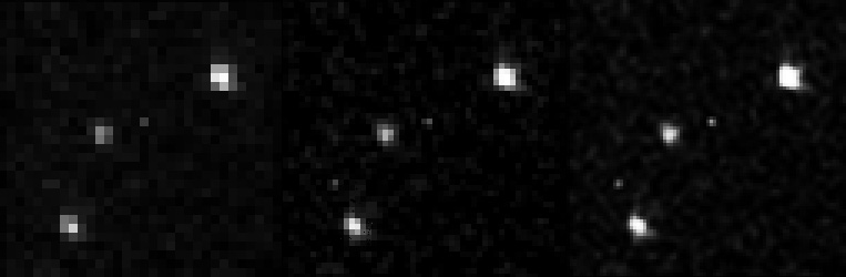
Most advice says that undersampling ― not allowing enough pixels for the FWHM ― should be avoided as it will make stars blocky and give the image a pixelated look.
Oversampling ― putting more pixels under each star than the critical sampling advises will yield more noise (because the signal from the target is weaker for each pixel) in the image and require more subframes or longer exposure per subframe compared to doing critically sampled imaging. Oversampling can also expose optical aberrations that fewer pixels would not reveal.
Overall, if you’re slightly over or undersampling and the image looks good: leave your setup alone.
In order to start dialing in the correct sampling for your seeing conditions, you need to calculate the pixel scale for f/# or focal length of the scope you are using.
Equipment Adjustment to Achieve Desired Pixel Scale
As the examples in the box above suggest, there are ways of modifying your pixel scale if the telescope/camera combination doesn’t match the chosen critical sampling criteria.
- Binning: dedicated astronomy cameras can combine pixels to create a virtual pixel that is larger in size. So a camera with 3-micron square pixels binned 2×2 will act as a camera with 6-micron square pixels.
- Reducer: Shortening your scope’s focal length with a reducer is usually done to achieve a wider field of view. However, it will also change the image scale to increase the amount of sky imaged per pixel and will reduce the number of pixels covering the FWHM of a star. See examples in Pixels and Sampling Equations box.
- Amplifier: increasing the focal length of the scope with an amplifier is often done for planetary imaging. But it also decreases the amount of sky imaged by each pixel. For example, adding a 2x Powermate to a scope will double the focal length and cause the camera to cover a stellar FWHM diameter with twice the number of sensor pixels. See example in Pixels and Sampling Equations box.
Comparison of Linear Size of Airy Disc, FWHM, and Depth of Focus
Depth of Focus (DoF) is the range between the converging and diverging light rays of a telescope over which the telescope’s center of field is in focus. For telescope with drawtubes, it is the distance you can move the drawtube and still be in focus at the center. If you locate the DoF equation on references meant for terrestrial lens photography, the equation can be complicated without more knowledge of the optics. However, for a telescope the equation is simplified because the distance from the lens to where the image forms is the same as the focal length at infinity focus and the circle of confusion (smallest spot a lens can produce) is the Airy Disc. Simple trigonometry can be used to find the distance between the converging and diverging light cones at infinity focus where the diameter of the cones are equal to the Airy disc as shown in the diagram here.

DoF= Depth of Focus (same units as Airy disc)
h) DoF = 2 * f# * Airy disc (this is for infinity focus only)
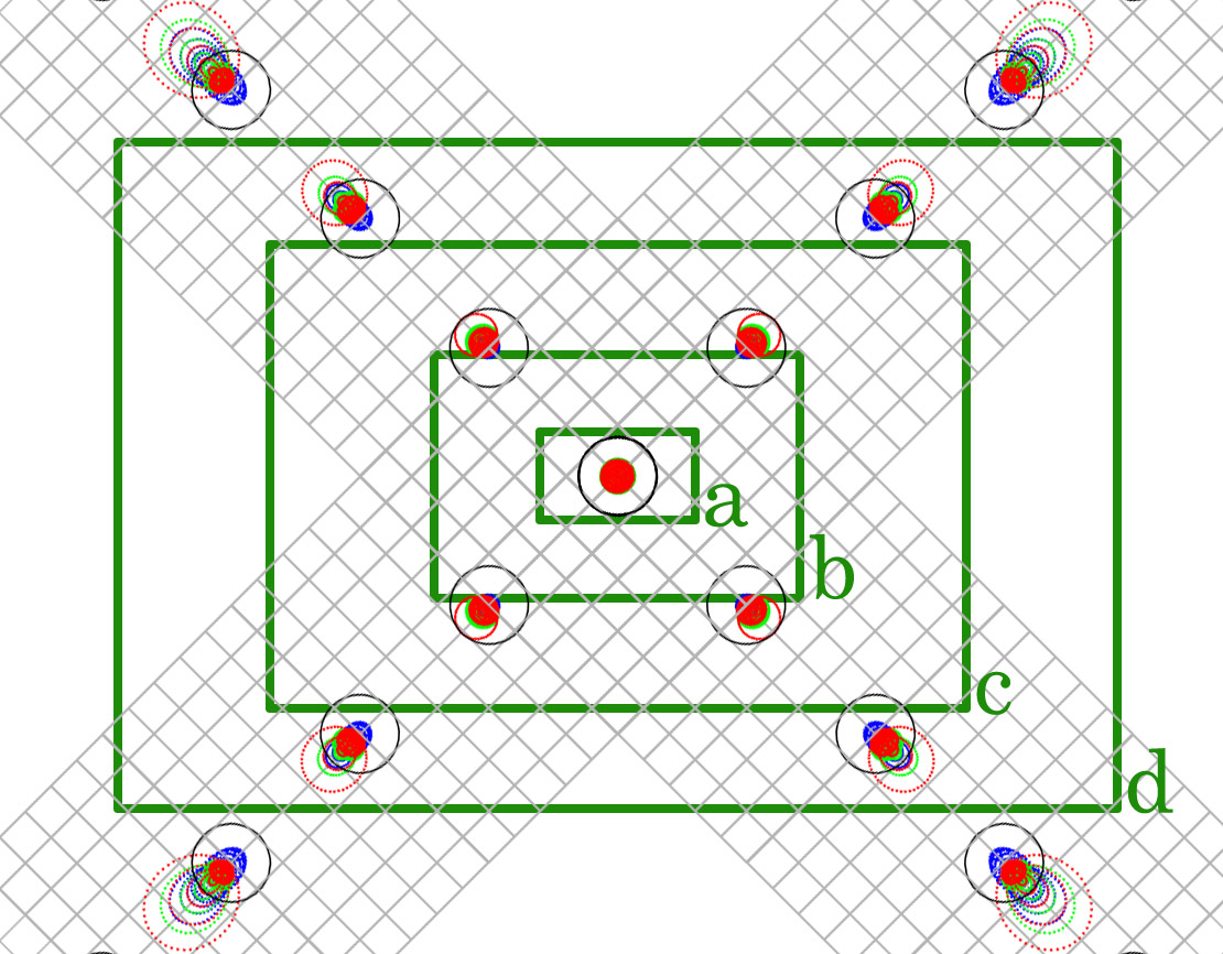
The Airy disc diameter depends on the observing conditions. So in bad seeing, with a large Airy Disc, the DoF is greater. Given the FWHM from imaging software, the actual size of the Airy disc can be calculated from equation c). For various focal ratio telescopes, the table below lists the minimum sizes of the theoretical Airy Disc each scope can produce, minimum FWHM of that Airy Disc, and minimum Depth of Focus in units of microns for yellow-green light. The two right most columns show the relative sizes of the Airy Disc with the FWHM and the Airy Disc with DoF.
| Focal Ratio (f/#) | Airy Disc (microns) | FWHM (microns) | DoF (microns) | Airy Disc (red) FWHM (green) Relative Size | Airy Disc (red) and DoF (brown) Relative Size |
|---|---|---|---|---|---|
| 4 | 5.4 | 2.2 | 43 |  |  |
| 5 | 6.7 | 2.8 | 67 |  |  |
| 7 | 9.4 | 3.9 | 132 |  |  |
| 10 | 13.4 | 5.6 | 268 |  |  |
While a fast imaging system is capable of producing small Airy Discs (observing conditions will dictate the actual size of the disc), the DoF is very small. Therefore, focusing is more critical in fast systems. On the other hand, an f/10 system produces a relatively large Airy Disk no matter the seeing conditions, offers a much wider DoF accommodation, but requires many more subframes to get the same exposure as the faster scopes.
Aberrations and Focusing
The depth of focus for an f/5.4 telescope is only 78-microns (0.07827-mm) for yellow-green light. That means your focus position can travel half that distance inside and outside of best focus and still yield sharp stars. While that is not a big amount, the good news is the best of today’s focusing stepper motors can move a drawtube in sub-micron steps. The bad news is there’s always atmospheric defocusing to consider. As previously mentioned, the shape of stars at the edge of the frame are far more sensitive to focus position because they do not defocus symmetrically like stars in the center. You can try to minimize corner defocusing by focusing on stars progressively toward the edge of the frame between images. See how far toward the edge you need to focus for improved corners without impacting the stars at the center of frame.
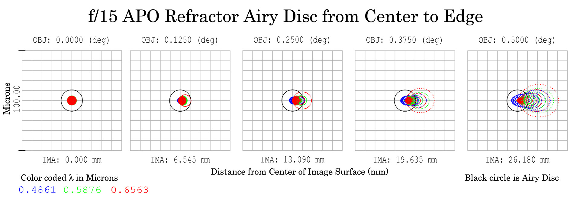
Edge Correctors
Every optical system has aberrations that increase as you get further away from the center of the field (off axis). These aberrations will cause a star to assume a non-stellar shape. You don’t see these edge aberrations visually because at a power high enough to see the diffraction limit, you are looking at a relatively narrow (on-axis) field of view. To actually view these outer field angles, necessitates using powers that are not great enough to resolve the diffraction limit. The larger the sensor, the more of the field will be imaged and since pixel size is the same across the sensor, the naturally occurring field aberrations are imaged at the same resolution as the center. (Note that bad seeing conditions defocuses starlight. Stars in the center of the field will simply grow symmetrically bigger, but stars in the corners will grow in shape according to the off-axis performance inherent in the optical design.) Accessories labeled corrector or flattener are usually employed to improve the edge performance of a scope for imaging. Depending on the size of your imaging chip and target, you may or may not need one of these.
Center of Field Imaging
For imaging planets, you’re only concerned with magnifying the center of the field where aberrations are minimal and smaller than the Airy disc size so they can’t be seen or imaged. You’ll probably employ a Barlow (mobile site) or Powermate (mobile site) to increase the effective focal length of your system to get planetary detail and crop the area around the target. So no edge corrector is needed.
Likewise, if you’re imaging faint galaxies and obscure planetary nebulae with a small-chip Deep Sky Object (DSO) camera, you’re likely only exploring the center of your telescope’s field and will not need a corrector.
Extended Objects with APS-C and Larger Chips
For larger field objects imaged with chips beginning at APS-C (30 mm diagonal) size, your corner aberrations might still be under control if you have large enough pixels — but require correction for small pixel sensor. For sensors bigger than APS-C you are most likely to need a corrector or flattener. You can also try slightly undersampling, by binning pixel size or reducing focal length as discussed earlier in this post, to reduce the appearance of aberrations in the corners.
Backfocus Requirements for Correctors and Reducer/Flatteners
One of the common problems in imaging is not respecting the required backfocus distance from the corrector to the image plane of the camera. For owners of Tele Vue Imaging system scopes, look for backfocus guidance in the Prime Focus section of the manual. If your manual is not up to date, you can download the latest version here. For correctors meant to work with non-Imaging System scopes, read the instructions for that corrector.
When calculating the backfocus length, make note of the following. For every 3-mm thickness of glass filter between the corrector and camera, add 1-mm to the required spacing. For example, if the required spacing from a corrector is 67 mm and there is a 4 mm thick glass filter between the corrector and camera, use 68 mm as the required spacing. From this distance, subtract the path length of any hardware between the corrector and sensor, including filter holders, off-axis-guiders, conversion rings, and the depth of the sensor behind the front flange of the camera. Use spacers to make up any remaining path length needed.
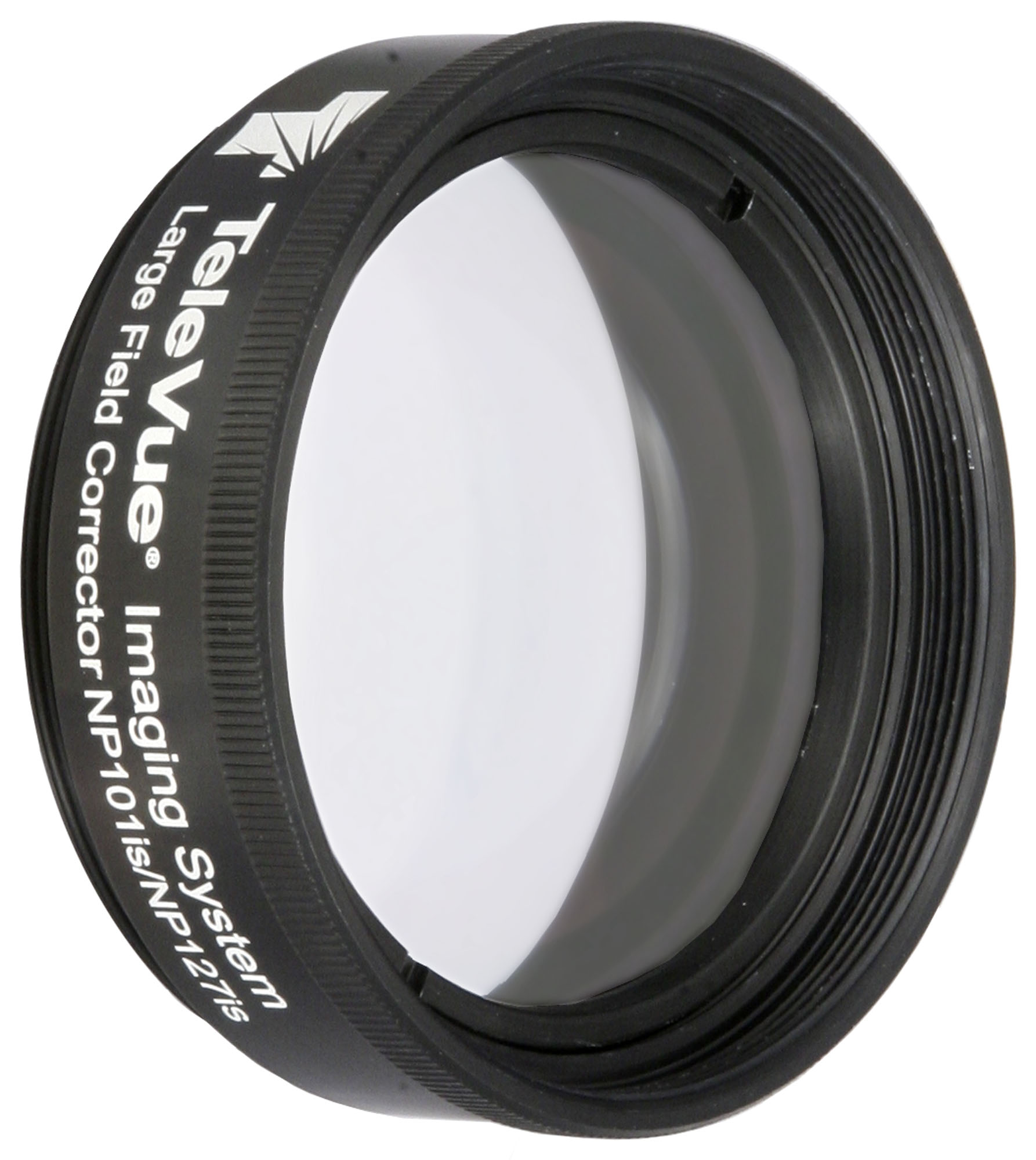
Our LCL-1069 Large Field Corrector (mobile site) optimizes images at the edge of field when imaging through the Tele Vue-NP101, NP101is, and NP127is telescopes. Recommended for cameras with diagonal sizes larger than APS format or cameras with pixels less than 6µm.
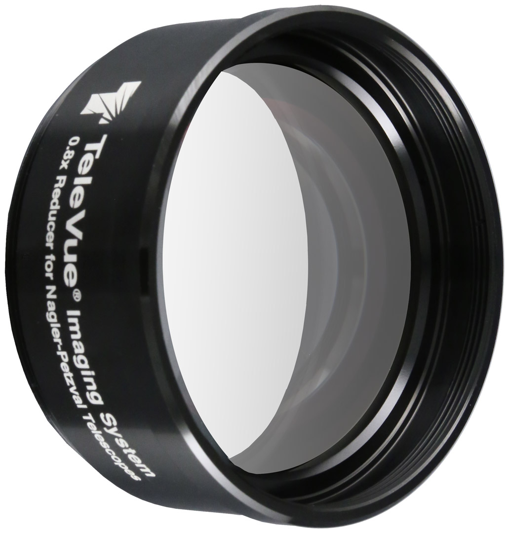
Model NPR-2073 0.8x Reducer for flat-field NP Scopes (mobile site) is specifically designed to be used with the Tele Vue NP127is and NP101is Imaging System telescopes. This reducer minimizes vignetting with camera sensors up to 43mm diagonal (Full Frame) and is a replacement for the previous 0.8x reducer, the discontinued NPR-1073 (which worked best up to APS-C sensors). The NPR-2073 reduces the focal length of the telescope by 20% and makes it that much faster. This increases the telescope’s field of view by 25%. For use on the NP101 with its 2-inch focuser, use Tele Vue Imaging System Nosepiece for 2″ Focuser (RAD-1074). The RAD-1074 slides into a 2″ telescope drawtube and has a 2.4″ Imaging System thread on the other side to accept any Imaging System accessory.
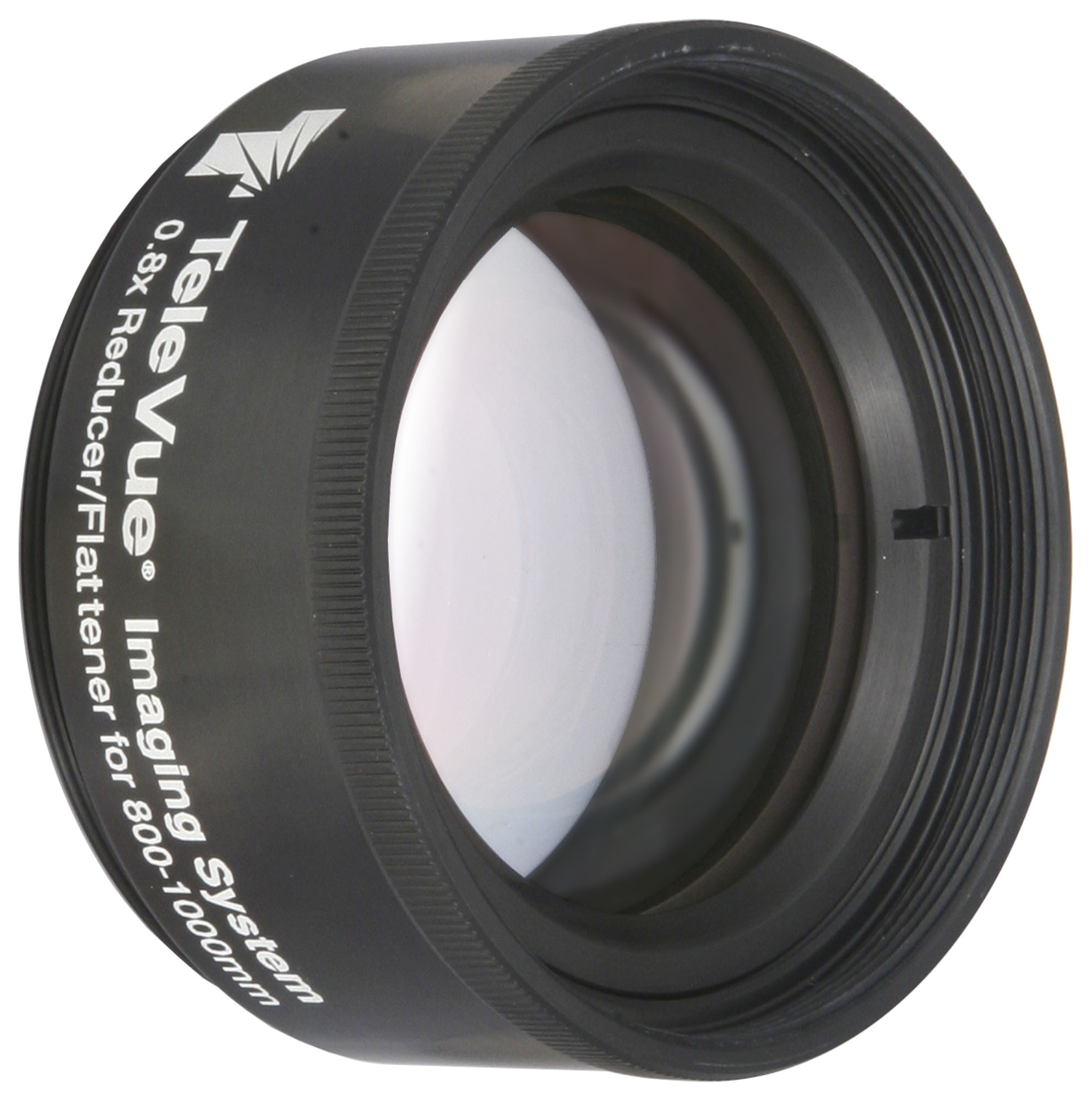
For any non-flat-field refractors from 800-1000mm focal length we recommend the RFL-4087 0.8x Reducer/Flattener (mobile site). It reduces the focal length by 20% while flattening it for 35mm frame formats. Scopes without Tele Vue Imaging System threads will require the RAD-1074 Imaging System Nosepiece for 2″ Focuser to adopt the RFL-4087 to 2″ focusers.
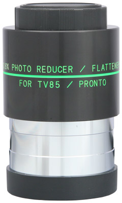
Model TRF-2008 0.8x Reducer/Flattener (mobile site) works with any non-flat-field 400-600mm focal length refractor. It converts Tele Vue-85 to 480mm f/5.6 and Tele Vue-76 to 380mm f/5.0 for flat field, fast photography. Fully multi-coated 3-element unit with 48mm filter thread inserts directly into 2″ focuser, accepts standard T-rings for 35mm cameras. With a DSLR and T-ring, the spacing from the flat flange of the TRF-2008 to the camera sensor is correct. With other types of cameras, you must use spacers to achieve the required 56mm backfocus distance.
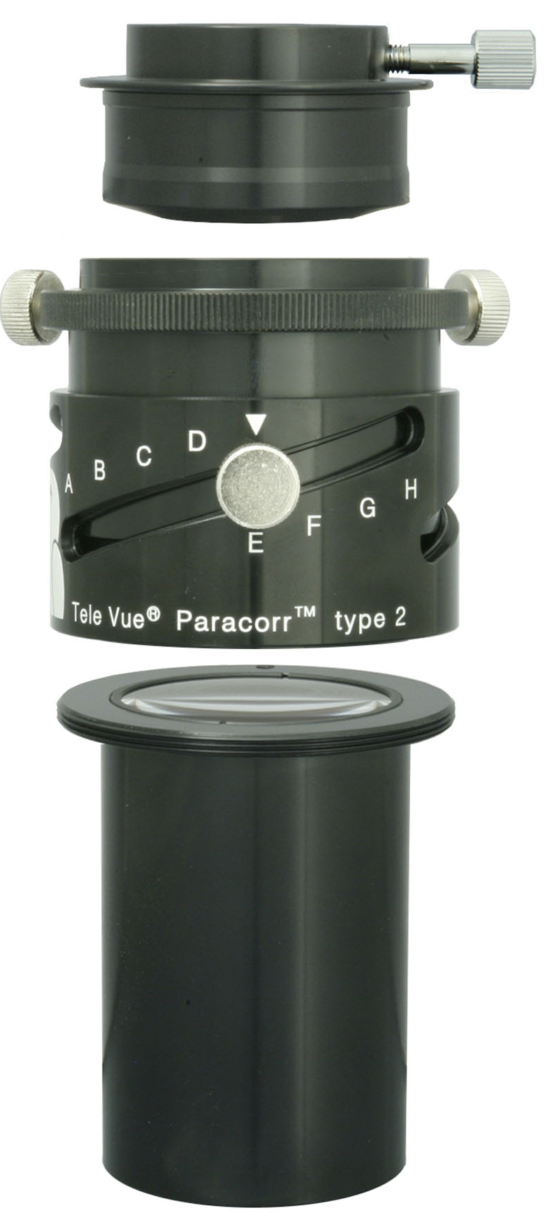
Our Paracorr Type-2 is a must for eliminating coma (comet-shaped stars) at the edge of eyepiece fields and corners of images made with your Newtonian telescope (mobile site). You can separate Paracorr’s optical assembly from the Tunable-Top used for eyepieces and use it with Tele Vue imaging system components to permit imaging with DSLR and astro cameras. APS size formats 27mm-diagonal or smaller are recommended to minimize field vignetting.
BIG Paracorr Type-2 is the 3″ version of the Paracorr designed for imaging with big chips (mobile site) and/or sub-f/4.5 focal ratios. Ideal for mirrors as fast as f/3, this is an essential accessory for wide-field imaging through fast Newtonians. See our blog post: Paracorr Type-2: Imaging the Skies with Luca Marinelli to learn an actual imager’s experience with Paracorr.
You can read the instructions for all these products on our Product List / Manuals page.

Adjusting for Tilt
If you zoom in on your corners and the stars appear worse in some corners, you might have some tilt in the system. This happens when the camera sensor is not perpendicular to the optical axis of the telescope.
For Tele Vue imaging system scopes, you can work this tilt out by putting your camera control software in live-view and using the jack-jam adjustments on the telescope end ring. This will tilt the sensor to fall squarely on the image plane. With a little practice, you’ll learn how to even out the corners.
Alternatively, your camera might have these adjustments. There are also aftermarket adapters (Camera Tilting Unit) with this feature.
Optical and Hardware Problems
You’ve done everything right and still have problems? You can have optical and hardware issues that need to be resolved.
If you think the problem is with your telescope because stars in the corners don’t look good but stars in the center of the field look okay, STOP. Your problem is not the telescope. Go back and try the suggestions above. If the stars in the center of the image look aberrated, continue reading. Diagnosing an optical problem starts with checking the on-axis collimation of your telescope. A star must look right in the center of the field before you move onto anything else. This must be checked visually and at high power. To do a star test follow this procedure. First, let your scope cool down outside to prevent tube currents from throwing off the test. On a night when the atmosphere is still, find a reasonably bright star (1st or 2nd magnitude), preferably near the zenith to minimize the amount of atmosphere you’re looking through. You will want to use an eyepiece that provides 150x or more to allow you to see the diffraction limit. Center the star and slightly defocus until you can see the star break out with two or three rings around it. If the rings are centered around the Airy disc, then your collimation is good. If the Airy disc looks shifted, meaning you see stronger partial rings on one side of the Airy disc and fainter or none on the opposite side, then you need to collimate your scope before you go any further. If the diffraction rings expand out from the Airy disc in an oval pattern on one side of focus and rotate 90° when you go through focus to the other side of focus, then your scope suffers from some degree of astigmatism. There are other optical aberrations that can be seen from studying the Airy pattern, but these are the two most common issues.
A floppy drawtube can be a culprit if corner aberration patterns vary as your scope tracks the sky. With today’s small pixel cameras, the amount of drawtube sag that will induce problems is too small to diagnose wiggling it by hand. Off-axis stars are most affected because of the greater displacement at the edge of the field versus the center. Tightening the drawtube lock screws does not solve the problem: it creates a pivot point for the drawtube to sag under the camera weight. To diagnose sag issues, take images of star fields at the zenith and then closer to the horizon. If the aberrations look different between these sets of images, you may have a loose drawtube.
Vibrating cooling fans on cameras have also been found to create elongated stars. The diagnosis here is simple: take a few frames with the fan running and a few frames with the fan off. If the second set of images shows better stars, the fan is the culprit.
Likewise, DSLR shake can be alleviated by setting the camera for a 2-second or longer delay after the shutter is triggered.
What else to check? There is so much advice online about these issues that we can’t cover them in this blog. Please read Sky at Night magazine’s online article Optical aberrations: how to fix errors in your telescope and Jerry Lodriguss’ Diagnosing Trailed Stars for examination of these issues.
Zooming the Corners
We started this blog by discussing how astrophotographers zoom their image corners to determine the overall image quality. It’s best to judge your image by the final result at 100%. So our advice is:
If you’ve made all adjustments possible and your corners appear fine at 100%: enjoy your images as they are!
Did you observe, sketch, or image with Tele Vue gear? We’ll like your social media post on that if you tag it #televue and the gear used. Example:
#televue #np101is #NGC7000 #deepsky
Do you want your Tele Vue images re-posted on Tele Vue Optics’ Social Media accounts? Use this hashtag for consideration:
More Info
- You can put Tele Vue in your imaging “corner” with one of our flat-field imaging scopes: NP101is (mobile site), NP127is (mobile site), and NP127fli (mobile site).
- Tele Vue Imaging System accessories (mobile site).
- Jerry Lodriguss’ AstroPix site has a compendium of Formulae for Astrophotography and Calculators for Astrophotography.
- Harry Nyquist’s Telegraph Transmission Theory (sampling rate) explained.
- About the Handbook of Astronomical Image Processing. The book appears to be out of print but can be found online.

