Watch Your Back Focus!

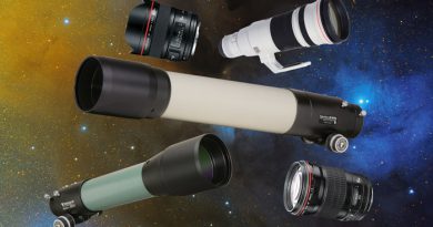
Optical Accessories for Imaging
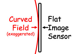
Most telescopes produce curved image surfaces, meaning that the focus at the center of the field is different than at the edge of the field. While your eye can compensate for some curvature of field, the flat imaging sensor on your camera can’t. So, telescopes can have either built-in or accessory flatteners to flatten the image plane for photography.
Reducers allow the scope to see a greater field of view by shortening the effective focal length of the system. This also naturally lowers (speeds up) the photographic f-ratio which in-turn allows shorter imaging times for non-stellar objects. Reducers are often combined with flattening correction to create a reducer/flattener.
For large sensors covering greater field angles, aberrations in addition to curvature become apparent toward the edge of the field. These can be fixed using correctors specifically designed for your telescope.
To function properly, all of these optical accessories require the camera sensor to be at a certain back focus distance from the correcting optic.
Tele Vue Refractors and Optical Accessories
Tele Vue Imaging System Refractors
Our Imaging System “is” refractors are based off the original 4-element, flat-field Nagler-Petzval designs but tweaked with larger rear elements and corresponding larger 76mm (3″) front aperture and 61mm (2.4″) rear aperture drawtube for greater edge illumination. This allows illumination for sensors up to 52mm in diameter with no effect on the excellent visual performance. As an aside, I.S. focusers are tested to hold 5.44kg (12-lbs) of weight. When used with typical APS DSLR cameras, these scopes need no additional accessory lens for correction. The rear group of lenses is located close enough to the focal plane to have a field flattening effect. This is ultra-convenient as the only “spacing” requirement is to be in focus.
Tele Vue Imaging System Optical Accessories
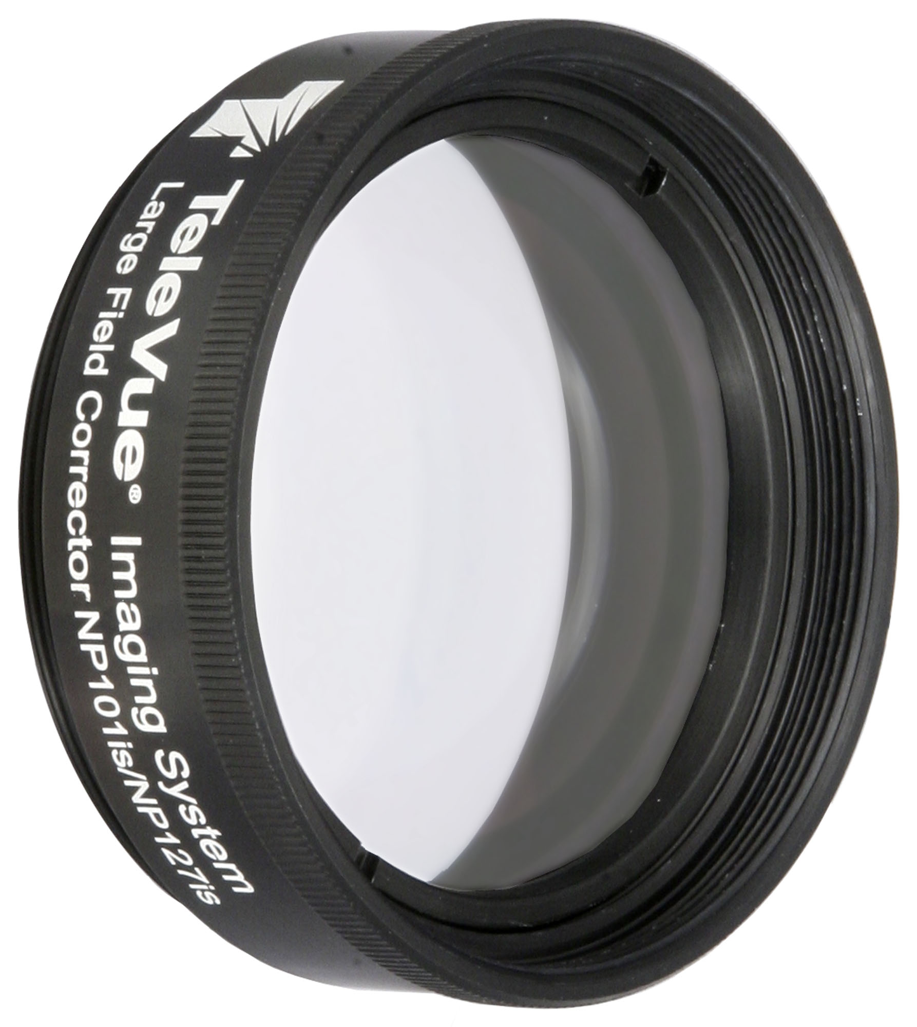
However, when sensors get larger or pixels get smaller, additional aberration correction is required. This is where the Large Field Corrector (LCL-1069) is used to optimize images at the edge of field. It is recommended for use with cameras with diagonal sizes larger than APS format — or for all cameras with <5µ pixel sizes.
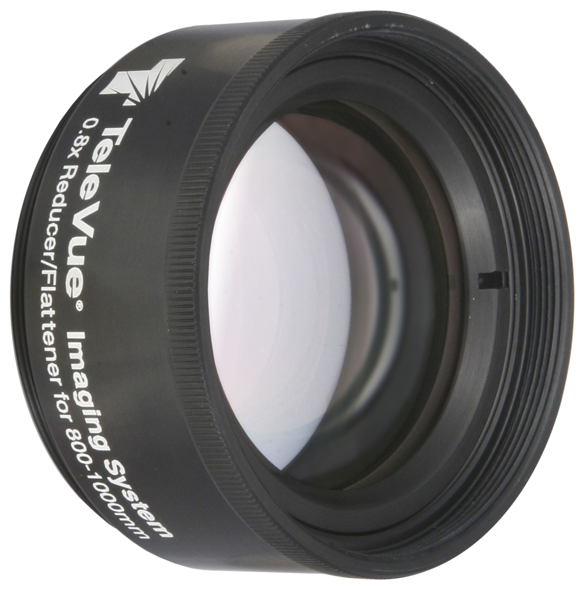
For longer focal length doublet scopes, our Tele Vue Model RFL-4087 is a 0.8x Reducer/Flattener (mobile site) for up-to APS-sized chips that works with 800- to 1,000mm focal length telescopes. It has the Imaging System thread but can be converted for use with any 2″ focuser by using the Tele Vue RAD-1074 I.S. to 2″ Focuser Adaptor. On the camera side, Imaging System adapters and spacers are used.
Short Doublet Refractors
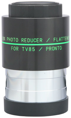
Any doublet objective scope with a focal length from 400- to 600mm and 2″ focuser is easily adapted for imaging with the addition of the Tele Vue TRF-2008 0.8x Reducer/Flattener (mobile site). For example, our Tele Vue-85 APO becomes a 480mm f/5.6 super-telephoto lens and Tele Vue-76 APO converts to a 380mm f/5.0 telephoto for flat-field, fast photography. This fully multi-coated, 3-element unit, with 48mm filter thread in the 2″ barrel, inserts directly into 2″ focusers, accepts standard T-rings for interchangeable lens camera bodies or astro-cameras with the correct spacers (55mm from back flange of TRF-2008 to camera sensor ) and T-ring adapter.
Steps to Determine Back Focus
Here at Tele Vue we often get asked how to achieve the proper back focus for imaging with our Imaging System optical accessories. This involves:
- Determining the Required Distance from Optical Accessory to Sensor
- Determining Your Camera’s Inherent Path Length
- Determining the Path Length of Accessories
- Determine Which Adapter will Connect to our Imaging System
- Determine Required Spacers to Reach Back Focus
In this blog, we’ll go through an example of how this is done.
1) Determining the Required Distance from Optical Accessory to Sensor
For optical accessories to work properly, the camera sensor must be located a prescribed distance from the optic. For Tele Vue Imaging System accessories, we use the flat surface at the base of the male threads on the metalwork as the reference surface since it is easy surface from which to measure. Traditionally, however, the Back Focus distance is measured from the center of the last lens surface to the focal plane. You must look at the instructions for the optic, or the telescope it was designed for, to learn what distance to set.
Continuing with our Imaging System example, the Large Field Corrector (LCL-1069) optimizes the edge of field when imaging through the Tele Vue-NP101is and NP127is telescopes. The “Prime Focus” section in the instructions for the Tele Vue-NP101is says to use a 69.85mm (2.75″) spacing for imaging sensor up to 43mm on the diagonal (full-frame) and 67.82mm (2.67″) for larger sensors. As we said, that distance is measured from the reference surface to the imaging sensor. In addition, if filters are used in the imaging train, for every 3mm of filter thickness, we recommend adding an additional 1mm to the back focus distance.

2) Determining Your Camera’s Inherent Path Length
Camera sensors are often recessed from a front reference surface on the camera. For DSLR and Mirrorless cameras, the addition of a T-ring makes the distance from the front face of the T-ring to the sensor an industry standard of exactly 55mm.
For dedicated astronomy cameras, you’ll have to read the camera manual carefully, look at the diagrams, and be prepared to contact the manufacturer with questions. For example, the ZWO ASI6200MM Pro is a popular cooled, full-frame, monochrome camera. We looked through the manual to determine how far back the sensor is recessed from the front of the camera. The “Camera technical specifications” table near the front of the manual says the camera has 17.5mm back focus. This means the sensor is recessed 17.5mm from the front of the camera. On a subsequent “Getting to know your camera” page, the camera is shown with a removable 5mm thick tilt adjust ring with M54 threads on the front. So, does that 17.5mm back focus measurement in the specifications table extended from the face of the tilt ring or the bare face of the camera? We kept looking through the manual and found the “How to use your camera” section showing attachment diagrams with the tilt adjustment ring on and off the face of the camera. With tilt adjuster attached, the diagrams show the back focus distance is 17.5mm and when off it is 12.5mm — the difference being the 5mm thickness of the tilt adjustment ring. So, now we know what 17.5mm back focus refers to the camera with the tilt plate and the 12.5mm back focus is without the tilt plate. The “Getting to know your camera” section states that the protective window in front of the sensor is 2mm thick. In an exchange with ZWO tech support, we were told that the back focus distances stated indeed accounts for the added path length of that window.
3) Determining the Path Length of Accessories
Imagers commonly employ at least a filter wheel/ filter drawer in front of the camera, perhaps an off-axis-guider (OAG), or atmospheric dispersion corrector (ADC) for planetary work. Going back to our ZWO ASI6200MM Pro manual in the “How to use your camera” section, there is an assembly diagram showing a typical setup consisting of the ASI6200MM Pro camera (tilt adjuster removed: 12.5mm) + ZWO-EFW 2″ Filter Wheel (20mm) + M68-OAG (17.5mm) + M54 tilt plate (5mm). This whole assembly from the face of the tilt plate back to the camera sensor has a 55mm distance. To attach this assembly to our TeleVue-NP101is with LCL-1069 requires the spacing to be 69.85mm + 1mm (assuming the filters in the wheel are 3mm thick) for a total of 70.85mm. This means we need to make up 15.85mm of spacing (70.85mm – 55mm).

Determine Which Adapter will Connect to our Imaging System
The first order of business is to choose an adapter to join the ZWO equipment to the Tele Vue imaging system threads on the NP101is using 15.85mm of path length or less. Because the last ZWO part facing the telescope side is the tilt adjuster with M54 thead, We’ll use the Tele Vue M54 Camera Adapter (M54-1073) for this. It has an M54 x 0.75mm male thread on one side and Tele Vue Imaging System inner thread on the other. Once joined to the M54 plate on the ZWO stack, the M54-1073 takes up 6.6mm (0.26″) of the path length so we are left with 9.25mm (15.85mm – 6.6mm) of path left to take up.
5) Determine Required Spacers to Reach Back Focus
In order to reach that final 9.25mm to back focus, we can use a Tele Vue 0.375″ (9.5mm) Accessory Tube (TLB-0375) for this task. It has outer and inner Imaging System threads to connect the M54-1073 to the Large Field Corrector (LCL-1069). You’ll notice that we went 0.25mm “long” with the back focus with this last part. Differences of a millimeter or less are not a problem. What is important is not to round off the calculations to avoid accumulated round-off errors.
Imaging System Adapters and Spacers
The Tele Vue Imaging System contains an assortment of adapters that connect cameras and imaging trains to Imaging System accessories.

The Imaging System also contains spacers from 1mm to 25.4mm in width.

Tip: Keep the Light Cone from Vignetting
Beware that narrow aperture accessories in front of the sensor may vignette the image. The problem diminishes with smaller sensors such as the popular 31mm (1.22″) diagonal APS-C chip. In our example, the ASI6200MM Pro has a full-frame sensor with 43.3mm diagonal. That’s why the ZWO 2″ filter wheel, that takes 48mm filters, is used in their example image train sequence and not their smaller 36mm or 1¼” filter wheels. Likewise, the M68-OAG and M54 tilt plate apertures are designed not to interfere with the wider section of the light cone encountered in front of the filter wheel.

Tele Vue Barlows and Powermate™ Amplifiers
The discussion in this blog concerned optical accessories for imaging with the widest field a telescope can show. However, sometimes you just need to go in the opposite direction: adding magnification for your telescope to enlarge a planetary image, Active Region on the Sun, or distant planetary nebula or galaxy. In other words, you need to increase the effective focal length of your telescope.
Our properly designed Barlows and Powermate™ amplifiers do wonderful things: they increase the effective focal length of your scope and slow the telescope’s focal ratio to reduce any curvature of field. Also, these accessories don’t require a specific back focus distance to work. You’ll just need to adjust your drawtube to reach focus.
Barlows

Great for framing the planets, Tele Vue Barlows use multi-coated high index glasses for optimum aberration correction, and exceptional contrast with virtually no light loss. Observed performance is aberration-free, even when tested with f/4 scopes. They even improve our competitor’s eyepieces and telescopes!

If your camera has a 1¼” or 2″ nosepiece, just insert it into the eyepiece barrel of the unit. If you have a T-ring on the camera, you can unscrew the Barlow chrome barrel and thread on a Tele Vue Bino Vue Flat Coupler (BVC-0125) adapter (spanner wrench slots facing out). This is a flat disk with Tele Vue Barlow / Bino Vue threads on the inside and T-threads on the outside. This can be ordered direct by calling Tele Vue Optics or asking your dealer to order it from us. This later method is the best way to save on shipping costs if ordering from overseas.
For more info see the Tele Vue Barlow page (mobile site).
Powermate Amplifiers

Tele Vue’s Powermate™ line has some distinct advantages over simpler Barlows for visual and imaging. Powermate™ photo / visual amplifiers increase the focal length of your scope with reduced aberrations, greater magnification potential, and compact size compared to typical Barlow lenses. Unlike Barlows, they don’t alter the eye relief distance of eyepieces and their magnification stays relatively unchanged regardless of distance to the sensor. Also, Powermates can be stacked with no adverse impact. Powermates are available in different barrel sizes and powers to meet your mission needs: 1¼” (2.5x & 5x) and 2″ (2x, & 4x) formats.
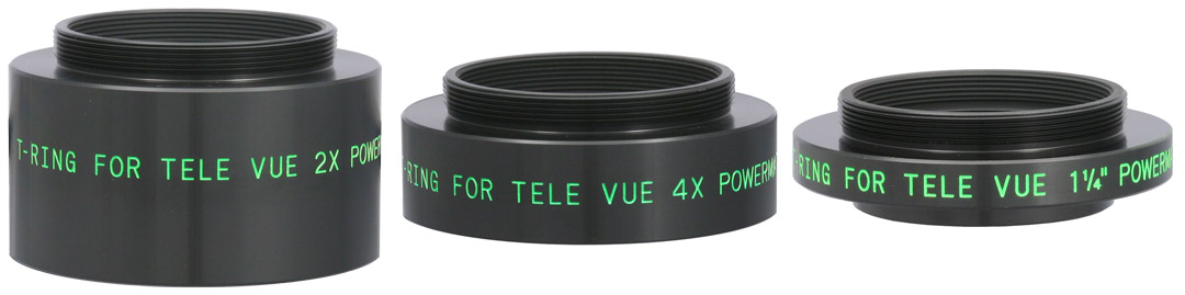
Imaging with Powermates is easy: the visual tops all unscrew to accept a specific Tele Vue Powermate T-Ring Adapter for use with standard camera T-rings.
Read more on our Powermate page (mobile site).Did you observe, sketch, or image with Tele Vue gear? We’ll like your social media post on that if you tag it #televue and the gear used. Example:
#televue #NP101is #heartnebula
Do you want your Tele Vue images re-posted on Tele Vue Optics’ Social Media accounts? Use this hashtag for consideration:
More Info
- Tele Vue Imaging System Accessory Table (mobile site).
- Tele Vue NP101is APO refractor for visual and imaging (mobile site).
- Tele Vue NP127is APO refractor for visual and imaging (mobile site).